How To Reduce Or Stop Machine Chatter
Machining operations can be disrupted by unintentional vibration known as "chatter," which occurs when the cutting tool interacts with the workpiece. Machine chatter can have negative effects on productivity, tool lifespan, and overall machining quality. By eliminating chatter, you can produce better parts, maintain consistent tool life, and reduce the occurrence of scrapped components.
Understanding CHATTER IN MACHINING
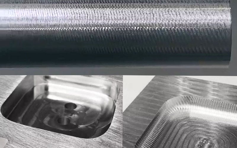
Chatter arises from an imbalance between the cutting tool and the workpiece during the cutting process. This imbalance causes the components to vibrate and collide with each other. As the cutting forces exerted by the tool on the workpiece reach resonance, self-induced vibrations occur. Chatter often manifests as loud noises and visible irregularities or "waviness" on the machined surface. These irregularities result from uneven tool-to-workpiece contact and varying cutting loads per rotation. There are two other types of vibrations encountered during machining: "Free Vibrations," caused by sudden motion changes during rapid traverse, and "Forced Vibrations", resulting from the intermittent cutting motion of a multi-tooth milling cutter or the rotation of an off-center part on a lathe.
CONSEQUENCES OF CHATTER IN MACHINING
Chatter in machining can have several detrimental consequences:
- Surface Finish: chatter adversely affects the surface finish quality and geometric tolerance of the workpiece, potentially leading to deformation. Often, if the workpiece is salvageable, the additional task of 'fixing' or re-finishing the surface with appropriate abrasives is required to remove evidence of chatter – requiring additional time, resources, and tooling.
- Cutting Tools: Excessive or uneven wear on cutting tools is another consequence of chatter, leading to premature tool breakage and compromising the overall machining process. Tool breakages can further limit reconditioning possibilities and increase consumable costs.
- Workholding: Chatter puts additional stress on workholding structures, including vises and fixtures, which must incorporate extra rigidity to withstand the forces generated by vibration.
- Machinery & Machine Tools: Persistent vibrations can damage dynamically moving parts of machinery, including gears, bearings, guide ways, and spindle assembly, resulting in increased wear and tear. Additionally, chatter can affect the long-term geometric and positioning accuracy of the machine tool, leading to additional repair costs. Machinists commonly respond to chatter by reducing speeds, feeds, or depth of cut, or by adjusting the tool path. However, these measures impact metal removal rates, reduce productivity, and compromise efficiency, especially in high-speed machining scenarios.
Different elements of the cutting process, such as the cutting tool, tool holder, workpiece, and machine tool, exhibit varying levels of stiffness, which affect the damping characteristics during cutting. Excessive cutting forces on a structure can lead to dynamic instability in the cutting process. For example, a slender tool or workpiece will respond differently to the same cutting conditions compared to a more robust counterpart. While eliminating chatter entirely may not always be possible, it can be minimized by addressing each element of the machining process.
Addressing Chatter In Machining
Cutting Tools
Cutting tools have a significant impact on chatter and are often the primary trigger. Therefore, selecting the appropriate tool for each application is crucial. Consider the following factors when choosing cutting tools:
- Determine when to use a solid carbide end mill versus an indexable tool.
- Choose a serrated edge (knuckle) or straight edge cutting tool.
- For solid carbide tooling, opt for unequal spaced flutes and variable helixes.
- Use stub tooling for shorter depth of cuts or longer tooling for deeper cuts.
- Select indexable turning inserts or indexable milling inserts with smaller nose radius, sharper cutting geometry, more positive rake angle, thinner PVD coating, or sharper uncoated inserts.
- Choose a tool with an entering angle closer to 90° or a lead angle closer to 0°.
- Check tool setup for incorrect center height or lack of rigid clamping inside the tool block, particularly for stationary applications.
Workholding
Pay attention to workholding methods that incorporate fixtures and clamping tools to prevent chatter. Design fixtures that provide overall structural rigidity to the workpiece, particularly in critical areas, while supporting weaker part features such as slender cross-sections or thin bottoms. Consider the direction of cutting forces to provide adequate damping and stiffness. Ensure robust clamping to prevent micro-movements caused by cutting forces. Secure the workpiece as rigidly as possible, using a milling vise with vise jaws or serrated teeth for enhanced gripping force.
In milling operations, ensure the right cutter pitch based on factors such as workpiece material, design, and fixture rigidity. Using the correct number of engaged teeth is essential to avoid harmonic imbalances. Adjusting parameters like radial depth, cutting geometry (serrated or rougher), or choosing tools with shorter cutting flutes can quickly eliminate chatter. In long tool overhang scenarios, opt for high feed milling with the lowest entry angle to reduce radial-deflecting forces.
Tool Holding
Toolholders, whether stationary or rotating, play a vital role in connecting the cutting tool, workpiece, and machine tool. Choose a holder with the shortest possible overhang and the largest possible diameter to minimize vibrations. Custom tool designs, such as tapered holders, can also be effective when the setup allows. For lathe tools, internal boring applications often present rigidity challenges. Consider the materials used in toolholders, as they affect static stiffness and damping behavior during cutting. Steel bars work well for length-to-diameter ratios up to 3:1 or a maximum of 4:1. When overhang lengths exceed this limit, heavy metal or carbide boring bars can yield good results.
In milling operations, pay attention to runout or total indicated reading (TIR). High runout precision is critical, especially in high-speed machining applications, as it affects chip thickness and load distribution on each cutting tooth. Minimize runout by ensuring clean spindles, collets, and holders to reduce interference between the cutting tool, holder, and machine tool. For longer connections between the tool tip and spindle face, keep the length to a minimum, particularly with modular tooling assemblies. Rigidly clamped tools perform best for high-performance machining applications with higher depths of cut and feed rates. Toolholders offering taper and face contacts are particularly useful when applications involve extreme radial forces.
Summary
Chatter in machining leads to significant productivity loss and can negatively impact workpiece quality, cutting tool performance, and the life of the machine tool. Minimizing and mitigating chatter requires careful consideration and tailoring of all dynamic elements.
Need Tech Support?
Our expert metalworking team can help you select cutting tools, toolholders and workholding solutions that can help you to reduce or eliminate chatter while machining. Contact the A&M Industrial Metalworking Team for product and application recommendations.